Since I've got nothing better to do, I've been out playing with some rockers
Now I don’t want to disappoint you, but probably not what you’re thinking. This kind of rockers.
Original Mini rockers are very inconsistent and within the same set we can have very different valve lift results due to their geometry. I’ve measured every single rocker I have and confirmed they do vary a lot. The procedure I’ve used was to get a cylinder head on the top of the block, set the (average) rocker geometry, forget about bush wear and then use valve no. 1 (exhaust valve) to test each rocker. This way I was able to swap rockers just by sliding them out of the end of the shaft without the need of undoing any of the pedestal nuts. Having that said, I had to adjust the rocker clearance (0.012″) for each rocker tested. This was a lot of trouble and I’m still not sure why I did that.
I guess I was looking for 8 rockers of the same type that were close enough to make a set. I was also looking or hoping (?) for those 8 rockers to be on the high(er) lift range… these aren’t really “high lift” rockers, but some are better than others. I’m pretty positive none of this makes much difference in a mildly tuned road engine, but… OCD sounds like a good justification.
While 1275cc pressed steel rockers were showing higher lifts, I didn’t have enough to make up a consistent set. The closer ones were actually a set of Spanish Authi rockers. I don’t know why I have those, but they look good and this is the only set of forged rockers I’ve seen made specifically for small bore engines.
The old bushings were a little bit worn so I managed to swap them and ream the new bushings to 9/16″. I did that on a small lathe I recently purchased and of which I might do a post in the future as I’m facing some challenges with it.
Anyway, all the main components are ready to be glued together, so let’s start with the block and gearbox.
While bolting the gearbox to the engine block is a quick and easy task, it is a significant one. Not only because we might feel that rush like the engine is almost ready, but also because we lose access to the “interior” of the engine.
Any mistakes done will give a lot of work to fix. For instance, if we drop a bolt or a washer into the gearbox, or if we forget to fit the O-ring for the oil pressure or the front half moon seal, that means splitting both components again and spend a good amount of time cleaning.
Even worse than that is when you take a second look to the workbench and realize the oil ring is right there… but you’re pretty sure you didn’t forget it. Then you start questioning if this is a second ring, or if you actually forgot to fit it. When that happens, and it will happen sooner or later, the right thing to do is to actually go through the work and check everything. And while you’re at it, check if all the rods and mains bolts were torqued to the correct setting.
The next step is kind of similar which is the fitting of the clutch housing. That will cover and block access to the drop gears, so before doing that, check if you’re not leaving anything behind. Paper towels, a couple of sockets, your swiss army knife…
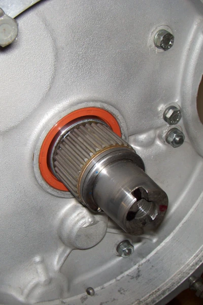
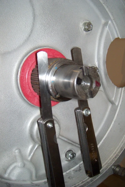
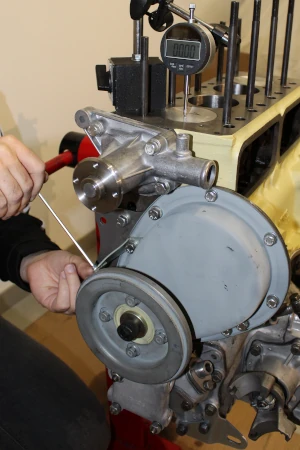
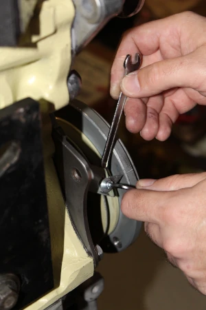
The idler gear, which is just barely visible through the primary gear hole above, runs between the gearbox face and the clutch housing. It’s function is to transfer the power from the flywheel to the gearbox – it acts like an intermmediate gear to make things spin the correct way. For that reason, it will be subject to some heat and thermal expansion and that’s why it needs some clearance to run – the books quote 0.003 – 0.006″. That clearance is normally checked with the clutch housing mounted to the gearbox – no engine, like the last image here. That’s when we get access to properly check the endfloat/clearance and if needed, easily swap the thick shims that sit at each side of the gear. It is assumed we use the same gasket (thickness of the gasket matters) and torque the bolts to the specified torque setting. I have made that exercise in order to have 0.0045″ of endfloat – that’s the value I wanted for this engine.
However, I tried to measure that now with the clutch housing bolted on to the block and that gap closed up 2 thou. The final endfloat is actually 0.0025″.
That’s a bit on the tight side, but the gear still feels right. Also I’m thinking that this 0.0025″ gap is accurate in the sense that nothing else will squeeze it and that measured clearance will actually be there when running. It might actually increase after the gear is pushed hard from side to side. In a way, this reading might be “more correct” than those taken with feeler blades when just the block and clutch housing are involved. Plus there should be a bit of cosine error with the DTI reading…
Well, I’m done trying to convince myself this clearance is OK. The gear feels fine to me, so against my own words above, I’m taking this risk and going forward.
Now is the correct time to torque the camshaft nut. In order to be able to do that, the camshaft needs to be locked so it doesn’t spin. We can lock the crank and cam, which are connected through the timing gears, by fitting the flywheel to the other end of the crank and slip an old mains shell between the starter ring teeth and the flywheel housing. Alternatively, there’s a tool with a tooth welded that can be bolted to the starter motor holes.
With the system locked, we can now torque the camshaft nut to 80lbft. In this case I didn’t use any lock tab, just a few drops of Loctite 243.
Re-checking the cam endfloat and just like the idler gear, the same thing happened – lost 1 thou with the final torque. In this case, I’m sure it’s fine, but this is an important remark for any future rebuilds.
The next photos show my home made pointer for the timing. Normally this is done on a Mini through the inspection hole in the clutch cover, but the space is not much and I think we are supposed to use a mirror to actually try to see the markings – it’s awkward and impossible if you have a servo fitted like on the Cooper S.
Anyway, I’m not fitting a servo but thought this would make my life easier, so I’ve added the pointer and marked the crank damper with TDC and BDC marks. Later I might add a range of degrees.
And we’re pretty close to have the engine finished. I will sort the tappet chest covers, the thermostat and oil filter housings, the oil pressure valve, the dipstick… and I’ll get back when it’s done.