
A naturally aspirated engine, like the A-series, is only as efficient as the air and fuel it can burn to produce power. Let me say that again: the more air and fuel we can squeeze into the cylinders and burn efficiently, the more power we’re able to get. Hopefully, we stop before something breaks.
Mini engines are known to have restrictive cylinder heads, thus limiting their capability to fill up the cylinders which in turn limits their power output. This is especially true with the standard 850cc (2A629) and 998cc (12A1456) small bore heads that have small ports and valves. In theory, these heads can be replaced with off-the-shelf heads like the 12G202 (with slightly bigger ports and inlet valves), the 12G206/129295 (with even bigger ports and inlet valves) or a big bore head to make our small bore engine breathe better, but then we have a few things to consider:
- Mechanical compatibility
While all unmodified small bore heads are interchangeable, a big bore head (or a small bore head with bigger valves) in a small bore block might require some attention. If the exhaust valves are bigger than the original 1″ valves, they will not clear the cylinder walls. So depending on how much they open, they might hit the top of the block and if that happens, sooner or later those valves will bend and brake. To prevent that, the easiest solution is to get some clearance by milling a pocket on the side of each bore. - Compression ratio
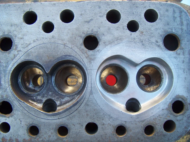
A standard 850/998 head has 24.5cc chambers, while the best flowing small bore head – the 12G295 – has 28.3cc. This 3.8cc difference is significant and if a direct swap happens, we will loose compression resulting in a less efficient power stroke and therefore losing power.On the other hand, the big bore head has just 21.4cc chambers and if used as is in a small bore engine, the compression ratio will increase. This increased compression might/will lead to excess of heat building up and that’s when detonation (pinging/knocking) starts to happen. Then all sorts of bad things will follow.
To address this, we might skim the head to decrease the chamber volume and therefore increase the compression ratio; or we might need to grind the chamber a little bit to increase the volume, lowering the compression.
-
Air velocity
In order to have good idling and a quick response in low revs, road engines normally have short duration cams. That means the inlet valves open late and close early in each cycle and that “duration”, which is the period the inlet valve is open, leaves just a small window to fill up the cylinders with air and fuel. Then there’s the behavior of the valve. It starts to lift off the seat slowly, following the cam lobe profile and not allowing much air to flow (the head of the valve is still covering the inlet throat), then continues to rise as the piston is going down faster, until it reaches max lift where it allows most air to flow – but! – it will only stay there for a fraction of the time. Then it starts to make the opposite journey returning back to the seat. We don’t get much airflow while the valve is opening or closing – it’s a progressive event and doesn’t work like a switch.
Now that we understand our window is very small and why filling the cylinder has to be fast, we might also understand that having large ports probably isn’t such a very good idea. Air velocity is slow on a large pipe.
But there’s more to it: a cylinder head port is not a straight pipe subject to the same constant pressure… and then there’s the presence of fuel, which is heavier than air… and let’s not forget that we need good fuel atomization. All the dynamics involved make this a very complex subject. If you’re curious, like I am, go and make a few searches online – there’s lot of information about this and by people better qualified than I.
Let’s just say that we might want to question if that big head with huge valves is the ideal for our small Mini engine. Of course, all of this ends up being a compromise, but if we take one thing from this subject, it should be this: heads and cams go hand in hand and bigger is not always better.

So I’m looking for a slight increase in performance for this 1047cc engine, but I’m also looking for reliability and driveability. That’s why I’ve chosen such a mild camshaft. Another requirement I have is looks: I don’t want this engine to look too much out of place in a 1961 car. For that reason, a big bore head is out of question and because I don’t want to skim 0.080″ (2mm) off of a 12G295 to bring the compression ratio back up, so is that cylinder head as well.
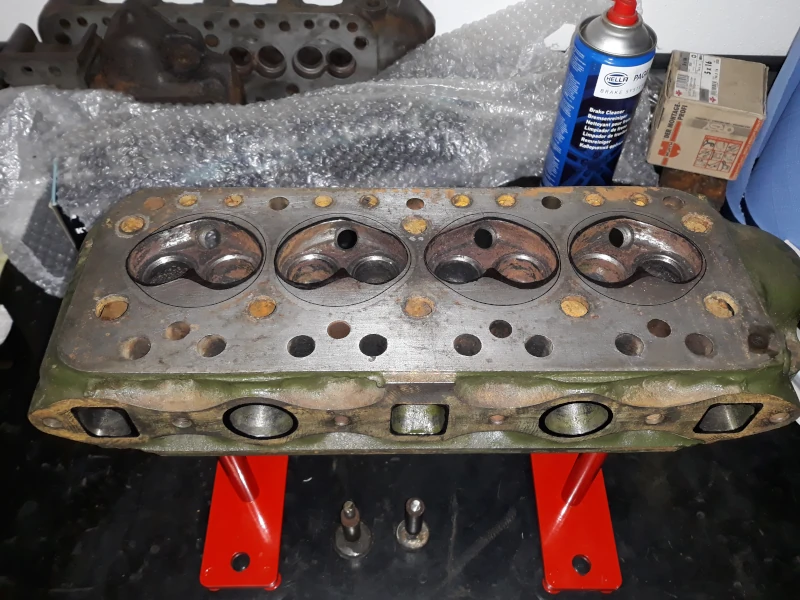
After going through a number of heads, I’ve decided to try a standard 998 head and make some modifications to suit the engine. People have been doing this since the early days and I thought that choosing a cheap head would be wise given this would be my first time modifying a cylinder head. If something goes wrong, I’m ruining a head that’s considered scrap anyway. Also, having small ports means more meat to play with.
But this one revealed a suprise. Someone had been playing with it before.


After some cleaning, I grabbed a manifold gasket, a cylinder head gasket and a template I made for the new chamber shape. Those were useful to layout the new shapes on the head.
Then I grabbed my mini-grinder, some cheap stones and started shaping.
I will not describe how I’ve done this as I don’t want to turn this post into a “how to modify cylinder heads”. Like I said, I’ve never done this before, I’m just familiar with some theory and curious about it. I’m not looking to dispute anything with anyone.
But knowing Mini engines respond really well to cylinder head modifications, I’m sure this will be fine. If not, I can always try to do another one… and to be honest, I already see a few things I would have done different today.
But hey, learning is a process, right?


The head was sent to the machine shop to cut 3 angle seats and fit bigger valves (1.250″ inlets and 1.060″ exhausts).
Since the exhausts are bigger than standard, I had to ensure they wouldn’t hit the block. A dry build allowed me to check that not only the 0.060″ rebore was enough to clear the valves – and allow for some valve guides wear – but at full lift the valve would still not reach the top of block. This was done without head gasket which should compensate for the skim needed to correct the compression ratio.
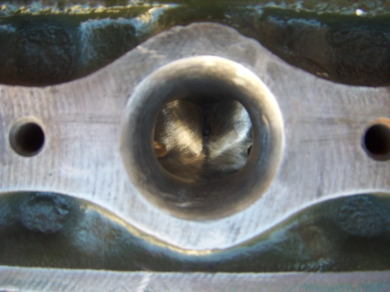
When I got the head from the machine shop I was’t impressed with the way they cut the seats. Most of the top angles weren’t there and the valves were not at the same height. I had a conversation with them and they said they were going to fix it… unfortunately, and I should’ve seen this coming, they only made it worse.

It’s clear they adjusted the cutter several times while making the cuts and while the exhausts now have some deep ridges, the inlets still don’t have top cuts. But hey, all exhausts are now at the same height, and so are all inlets. At this point, I was getting that “I know what you want better than you” attitude, so I decided to walk away from that machine shop. Like I said, it’s a cheap head and I’m glad I started with that.
I ended up trying to blend the seats by hand and realizing that maybe (probably) I’ll do another head in the future. Although this might be present me speaking, it will actually depend on how the engine will perform. I might stick to this and live with it.
As for the valves, I cancelled the back cuts the machine shop was going to do on the exhausts. If they can’t measure the width of a seat, they will not touch my expensive valves. Inlets already have back cuts ground in them.

With the valve job done, the next step was to measure the skim cut needed to correct the compression ratio.
I’m looking for 8.4:1 DCR to be able to use low octane fuel. DCR stands for Dynamic Compression Ratio and it differs from the usual (Static) compression ratio by only considering the useful part of the stroke, that is from the moment the inlet valve is closed and the piston starts to squeeze. For the static compression ratio (SCR) we use the full stroke of the crank – the one machined and hardcoded into the crank.
As a side note, the SCR is assigned to the engine when we build it and cannot be changed without a (partial) rebuild. The DCR, on the other hand, can be adjusted (to a point) after the engine is built, by increasing or decreasing inlet valves clearances.
Now to calculate the DCR we can use a long indicator to measure how much our piston rises from the moment the inlet valve is closed – that’s the dynamic stroke. Then we take that value and use it as the “stroke” in the usual SCR formula. Now we can resolve that in order to calculate the volume needed in our cylinder chamber to have the desired DCR. In my case, I’m looking for 26.8cc chambers.
To validate the DCR, I can now use the new cylinder head chamber volume to calculate the SCR. The result of that is 9.6:1 and since the cam manufacturer advertises 9.5:1 for this cam, it looks like my calculations are about right.


Using a burette to drop 26.8cc of dyed water into the chambers, I was able to measure the skim needed to achieve that chamber volume – 0.040″ or 1mm.
Then the head was skimmed and a piece of perspex was used to cover the chambers and actually measure if the total volume was correct or not. In this case, it was dead right at 26.8cc.
Putting all together is pretty much straight forward – valves go in the guides, then springs and top hats. Compress the springs and fit the collets that will hold the hats in place. Job done.
The only note here goes for the valve springs. Modern cams with higher lobe lift require modern springs that are thinner and do not crush on full lift. On top of that, they must be capable of providing the correct seat pressure. Having had the chambers modified and new seats cut, we need to check valve seat pressures as we might need to fit some shims under the springs to increase or machine the springs seats to decrease that pressure. In order to check that we must measure the space available in the head for the springs and then measure the spring pressure at that exact same length.
For this head I’m using a set of C-AEA525 springs and the seat pressures were around 70-80PSI. I called it good and moved on.


