
Two years into the production of the Mini, the 1961 850cc engine is still considered a very early engine where most of the issues known from the first years of production are found. Add 30, maybe 40 years of use and one can expect replacing a lot of parts in a rebuild.
IS IT WORTH IT?
Even if those parts are found in new or good condition, this engine will always have reliability issues related with the very early type of gearbox using cone synchromesh gears, the wet crank tail and the early clutch. Sure, there are conversion sets, but in the end an engine like this will also have little power and while that might be fun for a while, it also gets tiring. I believe that for this specific Mini, where originality is a third priority, there are better options.

This engine has been in my family since I can remember. It used to have a cylinder head on top, but it seems that in the last 10 / 15 years the bores were left exposed and even started collecting water from a broken window.
A few details tell us this would have been originally from a 1965 / 1966 ADO16 car, although it had (strangely) a Mini type remote diff housing that looked very original.
Anyway, I had the idea of using this 1098cc as the basis for the new engine. They are famous for their low down torque and the 1098cc engine is the biggest of all “small bores”, so capacity wise, the bigger I can fit in my Mini and still make it look somewhat “correct”. I want to avoid going “big bore” and keep looks similar to the original 850 engine.
However two things happened pretty much at the same time that made me change the plan. First, the 1098 crank was heavily scored. Second, I had the chance to get a good 998 crank with some work done by S.H. Engineering.
Since the 998 engine shares the same specification of cylinder block with the 1098 – the main difference between both engines is the crankshaft and pistons (in the 1098 the piston pin is in a lower position in relation to the top to accommodate the longer stroke of the crank) – this 12A497 block was still an interesting candidate.
A FEW minutes IN THE MAGIC POT AND THE BLOCK waS READY

Actually, not so fast.
Selecting single parts from different engines means none of them had been intimate before.
In fact, I don’t think any of the main components that make this new engine were ever in the same neighborhood. When this happens, it’s our job to get things started and make some introductions; check how they are getting along and how they play before they actually get married.
No assumptions and careful measurements are definitely in demand. So before dipping the block in the electrolysis bath and spend some money in machining, the viability of the block had to be addressed.
- First cleaning the bores. A rebore to +0.020″ would definitely not clear wear and pitting, +0.040″ was still questionable, so since I had to buy pistons, I went straight off to +0.060″. That increases capacity from 998cc to 1047cc.
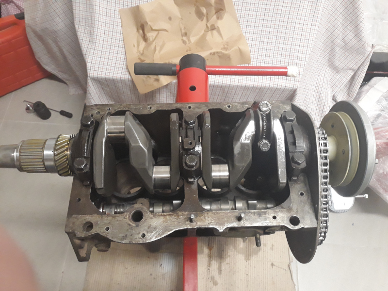
- Then checking how the crank fits. That means checking crank journals sizes and their corresponding housings in the block. Clearances were within spec, including bearings crush figures. The holes that feed the main journals had to be enlarged in the block as they were only half aligned with the bearing holes. This is quite usual.
- A dry build of the crank allowed to confirm it runs straight – less than 0.001″ run out in all journals.
- The crank end float was also addressed at this stage: 0.045″ – 0.005″ clearance was the target and the new thrust washers needed a skim.
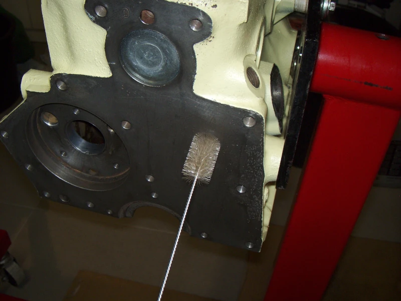
- Then all plugs removed, both from oil and water galleries to ensure we can clean all the gunk.
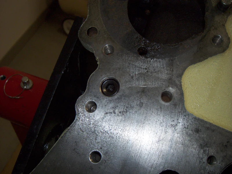
- Finally all threads chased and inspected for broken bits of bolts/studs at the bottom (believe it not, it’s not unusual).


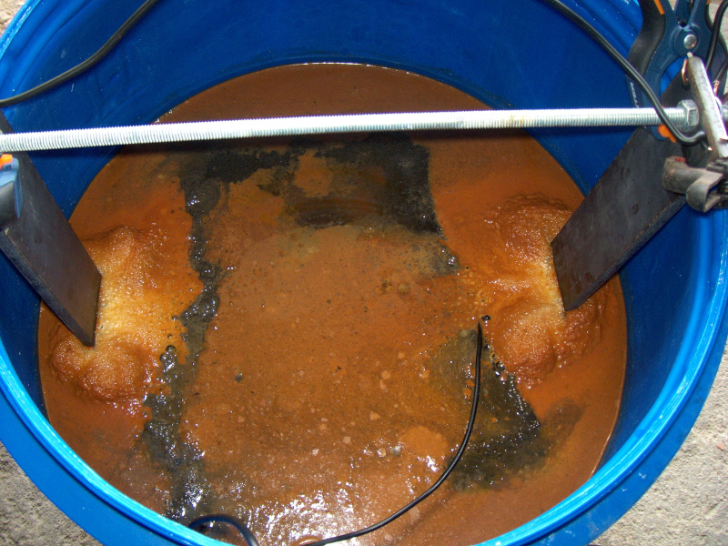
This was the first time I tried electrolysis in an engine block and I was surprised to see how well it worked. All the heavy rust was gone and the block was pretty clean afterwards. No visible damage in any areas, including the alloy 1100 tag at the back of the block and cam bearings which hadn’t been removed at that time. But, as soon as it started to get dry, flash rust started developing very fast, so if you’re doing this, have a can of WD40 at hand.

After the block was clean it was sent to the machining shop. Some holes on the top of the block were heavily corroded (water passages), so they were welded and closed a little bit. New cam bearings were installed, a rebore of +0.060″ was done (actually the size was piston size + clearance) and a fresh skim of the top left 5 thousands of clearance between the top of the block and the flat top pistons at TDC.
The oil gallery ends were tapped – 14mm at both ends of the block and 5/16″ at the bottom. Doing this, the brass plugs could be replaced with grub screws as that’s just makes it easier to clean up the gallery in case of future need.

Meanwhile I was getting the rotating assembly ready for dynamic balancing. This is generally good practice, especially when using new parts or used parts from another engine. In this case, I was using a new flywheel / clutch and also a new crank pulley and damper combination (the same used in the Cooper S). These parts do not come balanced off the shelf and if they happen to have a small inbalance, it might be reflected as a big inbalance as the revs go higher and centrifugal force increases. Getting this assembly balanced will reduce the chance of having those big vibrations and improve the overall smoothness of the motor. This is done, of course, up to a certain degree.
Replacing the old flywheel just makes sense. We get a new starter ring, a newly machined surface for the clutch disc and the best part, it weighs only 4.5Kg (9.9lb). That’s a 40% reduction of weight in one single component comparing to the old cast iron flywheel with 7.55Kg (16.65lb). The old cast iron back plate was also replaced with a new steel (EN8) back plate. Both these new items are suitable for road engines, they are not race (feather weight) items. The goal is to save some weight and get the engine to accelerate and slow down faster, but not to go to the extreme of losing momentum as we go.
But before having the balancing done, the clutch had to be prepared. We are looking into having the diaphragm spring sitting flat (parallel or even 5 thou concave to allow bedding in / wear) against the flywheel when stationary, that’s where the system is optimized in terms of maximum holding pressure and least amount of effort to release the clutch. To achieve that, normally we need to adjust the height of the 3 back plate feet. Being a new back plate, mine had to be skimmed 0.055″ (1.40mm).
Smaller parts like the primary gear were also checked at this stage to ensure correct running clearance and endfloat. The same for the crank sprocket and its alignment with the camshaft gear. I wanted to make sure nothing had to be changed after having the whole lot balanced.
Then I tried to center all the parts in the clutch assembly. For that I used the crank with the primary gear as a centering device. The flywheel was the easy part as it’s a tapered fit, but for centering the clutch disc I used the primary gear (it will never have a fixed position, so that’s as far as we can go) and for the back plate and “blue” diaphragm I used a DTI to check the runout and center the parts the best I could. The same exercise was done to the crank damper (front side of the engine). Finally all bolts were torqued to final spec and loctited, where applicable. These are the steps I thought worth doing to optimize balancing the parts without actually modifying them.


From the balancing point onwards, the clutch assembly and crank pulley/damper were handled as single components. No more taking them into bits as that would disturb the relative positions in which they were balanced. To fit the flywheel and torque the big bolt at the end of the crank, I’ll be removing the thrust bearing plate which is just held by a spring.


The rods above were selected because they were the best set of rods I had in terms of sizing and straightness. They’re spot on. They had a previous attempt of someone lightening them, noticeable in the narrower big ends which were turned in a lathe, but they were not finished and were generally very rough.
I finished them by hand, balanced end to end and overall, and gave them a polish. You can see the difference between a non modified rod and the ones I’ll be using in the photo above. They were made for floating pins (small ends bushings) and this engine could do better with a set of press fit type of pistons, but all I had were of this type… and these were what I used.
In the next image you can see me cleaning the oil ways of the crank to make sure no chips or grinding dust is trapped inside which could damage one or more bearings when the engine picks up oil pressure.
What is also visible is the shiny marks where the bearings ride after the dry build checks. The clearances are spot on (0.012″) and none of the rods ride on the journal (small) fillet radius. I’m happy with this, let’s put it together!
